ayatec logo
Home Store Blog Contact
unicontrol user guide by ayatec
Home Store Blog Contact

Topics

  1. Welcome
  2. Getting started
    1. What is unicontrol
    2. How it works
    3. Connectivity
    4. Integration options
    5. Default hardware
    6. Hardware extensions
    7. Special sensors
    8. RGB driver
    9. Audio driver
    10. Network API - HTTP
    11. Network API - MQTT
    12. Network security
    13. Downloads
  3. Web Interface
    1. Processes
      1. Process
      2. Name
      3. Main state
      4. Initial state
      5. Display
      6. Constraints
        1. Process timer
        2. Variable contraints
        3. Force output
      7. Input
        1. Input source
        2. Channel
        3. Control period
        4. Value
        5. Publish
        6. Frequency
        7. Subtopic
      8. Events
        1. On/Off event
        2. Condition
        3. Idle/running time
        4. Delay on/off
        5. Fade in/out
        6. High/low input
        7. Mid point/Tolerance
        8. Out on when
      9. Output
        1. Primary output
        2. Action
        3. Type
        4. Invert
        5. Duty cycle
        6. Mem value
        7. High/low output
        8. Folder/Track
        9. RGB mode
        10. RGB color
        11. RGB brightness
        12. RGB speed
        13. Publish
        14. Subtopic
        15. Secondary outputs
      10. Cycle
        1. Cycles
        2. High/Low phase
      11. On/Off button
    2. Peripheral
      1. Hardware
      2. Type
      3. Calibration
      4. Mapping (edit)
      5. IR remote (edit)
      6. Impulse_counter (edit)
      7. RGB driver (edit)
      8. DS18B20 (edit)
    3. Device
    4. Network
    5. System
    6. License
  4. Tutorials
    1. First boot
    2. First process
    3. Connect to MQTT
    4. Process sequencing

    5. DIY Project: Bath Fan

In this article

  • Introduction
advert
unicontrol > Web interface > Peripheral > Impulse counter (edit)

DS18B20 (edit)

Introduced in version 1.11

Each DS18B20 possesses a unique 64-bit serial code, allowing them to be individually addressed when connected on a single wire. The codes of identified sensors are stored in the memory of unicontrol and are utilized upon each subsequent boot. As a result, each sensor maintains its Input Channel position regardless of any changes to other sensors. When a DS18B20 is selected as a Peripheral, the Edit button becomes available:

Open the DS18B20 editor.

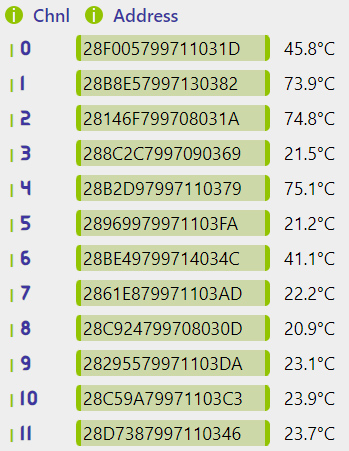
Clicking this button navigates the user to an editable list of known sensors. Their current temperature readings are also included for easier identification:

Fully populated list of DS18B20 sensors.

There are specific rules for how the Channels are assigned:

  1. Positions of all previously saved sensors are retained.
  2. A newly identified sensor is automatically assigned the lowest unassigned Channel position.
  3. If all 12 positions are occupied, the new sensor will not be used.

Based on these rules, here are several guidelines for working with the DS18B20:

  • Initially, connect all sensors to the desired GPIO pin, then either re-initialize (Save) the Peripherals or Reboot the device. This action will auto-populate the Channels with the connected sensors, starting from 0.
  • If a different order is desired, users can copy/paste the displayed codes between the Channels.
  • When removing a sensor, its code must be manually deleted from the list. Failing to do this means its position will remain reserved indefinitely, potentially preventing new sensors from being utilized.
  • Upon adding a new sensor, it is automatically assigned to the lowest Channel without a saved serial code. Hence, it may not necessarily appear at the end of the sensor list. Subsequently, users can reassign it to any position they prefer.
© 2024 ayatec.eu • Found a mistake?  Let us know!