
Impulse counter (edit)
A built-in impulse counter can be used to utilize a wide variety of pulse sensors. A standard pulse sensor works by sending short impulses over its data pin, with each impulse having a constant predefined physical-world interpretation. To translate the impulse counts into the interpreted quantity, the unicontrol lets the user define this interpretation in the Impulse counter editor. This interpretation is provided in two parts:
- Number of pulses corresponding to a single unit of measurement, and
- Unit of measurement in which the specific sensor's measurements are defined (e.g., liter, gallon, meter, etc.). This is only used for displaying purposes within the web interface but does not have any quantitative impact on readings.
Option 1:
Pulses:
50
Unit:
liter
All measurements will be expressed as the number of liters flowing through the sensor per minute.
Option 2:
Pulses:
5
Unit:
dl
All measurements will be expressed as the number of deciliters flowing through the sensor per minute.
Option 3:
Pulses:
191 (approximately)
Unit:
gallon (US)
All measurements will be expressed as tens of US gallons flowing through the sensor per minute.
Editor
After initiating the Impulse counter in the Peripheral page,
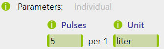
clicking the Edit button below the Hardware drop-down menu lets the user define the pulse sensor parameters:

By default, only one Pulses/Unit pair can be filled in and will be used for all initiated counters. This situation is suitable when all counters are monitoring the same type of sensor.
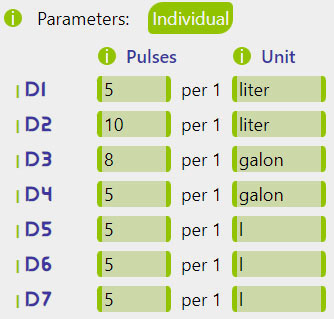
When activating the Individual switch, each counter can be assigned a separate Pulses/Unit combination:
Process
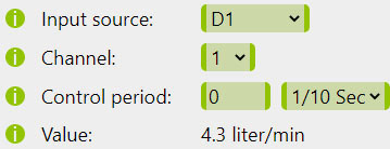
Once the Impulse counter input is fully set up, it can be called within the process by selecting the relevant digital pin as an Input source. Each Impulse counter pin carries two different values at all times, which can be differentiated by the Channel choice:
Channel 0contains the instantaneous reading calculated as the number of impulses recorded in the last second, extrapolated to impulses per minute, and transformed into the required Unit of measurement.Channel 1contains the exact number of impulses recorded in the last minute, transformed into the required Unit of measurement.
While the instantaneous (Channel 0) reading is an estimate and can be published at any frequency,
the 60 second (Channel 1) reading will only accumulate the readings precisely if a 1 min. increment is chosen as a frequency.
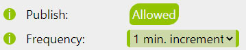
1 min. increment publish frequency will only publish the message with readings once the latest reading is ready,
ensuring that no impulse is counted twice or missed out. Also, please note that:
- Messages may not be sent in exact 60-second intervals, but they do contain readings accumulated over exactly 60 seconds. Assuming there are no disruptions, this will result in an accumulation of approximately 3600 messages per 24-hour period.
- Precision is lost in case of power loss or reboot. It is advisable to ensure a stable power supply and schedule automatic maintenance reboots at a suitable time.