
API - HTTP
The unicontrol HTTP API provides a convenient way of integrating devices with this software into any existing ecosystems and platforms. It offers a RESTful interface that allows accessing unicontrol features from a third-party software. In this guide, you will find a detailed technical specification of the various endpoints, commands, and parameters available in the API to help you get started. Whether you are new to unicontrol or an experienced user, this guide will provide you with the essential information required for successful implementation.
Unlike MQTT or Serial communication , HTTP API is designed to allow the user to have a complete control over all aspects of the device.
In the broadest terms, to access the required resource, the user needs to send an HTTP GET or HTTP POST request to the local* network URL:
http://[IPv4]/[resource]
To find out more about available resources please see the following Telemetry, Parameters and Commands sections.
Addressing the process
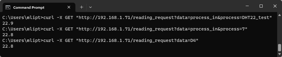
Addressing process can be done in two-ways: the [PROCESS ID] placeholder can be replaced either by the respective process' Name or its index number
(all available processes are numbered starting from 1 and ending with a total number of processes - either 5, 15 or 40, depending on the software version).
For the HTTP requests both options can be used equivalently at the same time as long as the processes' Names are defined unambiguously.
"5" is possible, but addressing it this way will cause the software to operate with the process #5 instead.Telemetry
To obtain the required telemetry data as a response, the user needs to send an HTTP GET request to the following URL:
http://[IPv4]/reading_request?data=[TELEMETRY]&process=[PROCESS ID]
HTTP API access to the telemetry data listed below is available in all unicontrol versions.
| [TELEMETRY] | Payload | Note |
|---|---|---|
D0-D8 |
numeric reading (if input) 0 for LOW, or 1 for HIGH (if output) |
If input: Returns current reading as a plain numeric value in the predefined unit (unit symbol not included) If output: Returns current state of the output If system: If the chosen peripheral is used as a system port, the request will return a string "System". |
RE1-RE12 | 0 for LOW, or 1 for HIGH | Returns current state of the output |
I1-I8, A0 | numeric reading | Returns current reading as a plain numeric value in the predefined unit (unit symbol not included) |
MEM1-MEM8 | numeric value | Returns current value saved in the respective memory slot |
process_in | numeric reading | Returns current reading of the chosen process' input. |
process_out | 0 for OFF, or 1 for ON | Returns current state of the chosen process' output. |
in_out_all | JSON | Returns basic summary of all physical peripherals D0-D8, A0 and I1-I8 containing current reading or state and unit (if applicable). [PROCESS ID] not relevant. Please note that A0=I1. |
Parameters
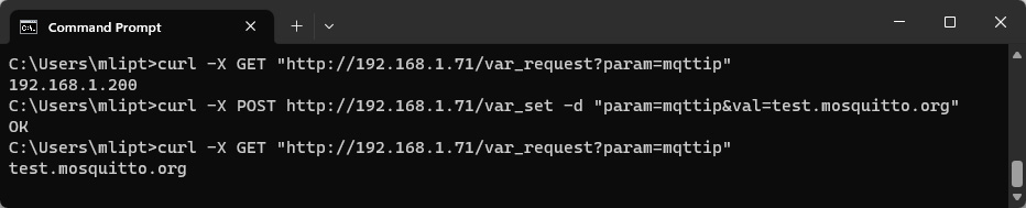
To set or change the selected parameter, the user needs to send an HTTP POST request to the following URL:
http://[IPv4]/var_set?param=[PARAMETER][SUFFIX]&val=[VAL]
To obtain the selected parameter's saved value as an HTTP response, the user needs to send an HTTP GET request to the following URL:
http://[IPv4]/var_request?param=[PARAMETER][SUFFIX]
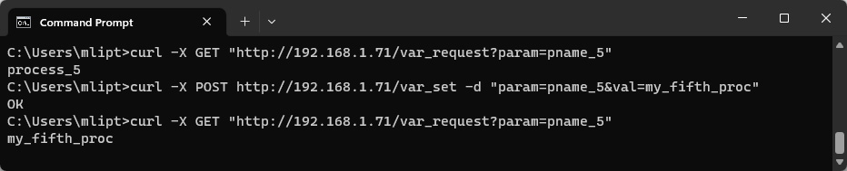
For the process variables the [SUFFIX] must be replaced with a string constructed from "_" followed by respective process' [PROCESS ID].
For example, when addressing the Main state of the Process 5 the variable must be referenced as mstr_5.
In case of other than process variables the [SUFFIX] must be left out.
System settings
HTTP API access to the system variables listed below is available in all unicontrol versions.
| [PARAMETER] | Default value | [VALUE] | Description |
|---|---|---|---|
Name (devicename) | my_uni | String of up to 25 characters | Name of the device used for its easier identification in the network. It is also used as an SSID in case of the Wi-Fi AP mode. |
SSID 1 (ssid1) | aya_ssid | SSID names of the primary and secondary 2.4GHz Wi-Fi access points to connect to. Connection to the secondary network is only attempted if the primary network is not accessible and uses parameters automatically assigned by the router. Please note that 5G bandwidth networks not supported. | |
SSID 2 (ssid2) | empty String | ||
Password 1(pass1) | aya_pass | Wi-Fi Password to the SSID 1 network. | |
Password 2(pass2) | empty String | Wi-Fi Password to the SSID 2 network. | |
User (mqttuser) | mqtt_user | SSID name of the selected 2.4GHz Wi-Fi access point to connect to. Please note that 5G bandwidth networks not supported. | |
Password (mqttpass) | mqtt_pass | Client password to the MQTT broker. | |
Topic L1 (topicL1) | my_uni | Defines up to first 3 subtopics of the topic strings used for communication with the device via MQTT protocol. While the 1st level is mandatory, 2nd and 3rd are optional and are used for a unique identification of the user. Should not contain special characters. Learn more... | |
Topic L2 (topicL2) | empty String | ||
Topic L3 (topicL3) | |||
Password (masterpass) | passw123 | Device administrator password for extended access. This password is also used to access the device in Wi-Fi AP mode, but needs to be at least 8 characters long to work properly. Learn more... | |
Origin(CORS) (origin) | null | String of up to 45 characters | Origin of the web interface from which the device will be accessed. Keep null when using an offline local copy of the interface or the app. |
Default Wi-Fi(1.15)(wifimode) | STA | 0 for STA or 1 for AP or 2(1.16) for Off | Determines the default Wi-Fi mode in which the device begins following the boot.
In the STA mode the device will try to maintain a connection to one of the saved wireless networks.
In the AP mode the device will serve as an independent Access Point, allowing other wireless devices to connect to it.
In the Off mode the Wi-Fi is disabled, but the device will only boot into this mode if the System button is defined on I8.
The three modes can be arbitrarily switched during runtime. |
IP Mode(wifiauto) | Dynamic | 0 for Static or 1 for Dynamic | Enables or disables dynamic assignment of local network IP address, Gateway, Subnet mask and DNS by the router. Static implies that user-provided values are prioritized. |
IPv4(Wi-Fi)(localip) | 192.168.1.255 | IPv4 address in the standard decimal format x.x.x.x | Device's local network IP address. Only applicable if Static IP Mode is selected and only used if the provided address is available. |
Gateway(gateway) | 192.168.1.1 | Local network gateway. Only applicable if Static IP Mode is selected. | |
Subnet mask(mask) | 255.255.255.0 | Local network subnet mask. Only applicable if Static IP Mode is selected. | |
DNS(dns) | 8.8.8.8 | IP address of the preferred DNS server. Only applicable if Static IP Mode is selected and an internet connection is available. | |
IPv4(MQTT)(mqttip) | 192.168.1.200 | Internal or external IP address of the MQTT broker. | |
Port(mqttport) | 1883 | integer between 0 and 65535 | Listener port of the MQTT broker. Only non-SSL listeners are supported. |
Connection(mqttallow) | Disabled | 0 for Disabled or 1 for Enabled | Allow or disable connection to the MQTT broker for publishing sensor readings, output state changes or remote control. Learn more... |
Subscription(suballow) | Enabled | Allow or disable subscribing to and receiving MQTT messages for remote control via MQTT | |
Webprotection(secure) | Disabled | Allow or disable password protection for web access. Only keep this Disabled if the device is not accessible outside of your secure and trusted network.Learn more... | |
Extended serial(serial) | Enabled | Allow or disable receiving of the Serial port commands. Keep this disabled at all times if physical access to the device is not restricted! Learn more... | |
Display(display) | Show all | 0 for Show all or 1 for Hide system info or 2 for Hide all | If physical access to the device is not adequately restricted, the user can use this setting to hide either System or All information from the Display loop. |
Time-zone (timezone) | 0 (UTC) | selection of integer between -12 and 30 | Time-zone relative to UTC in which the device's real time clock should be referenced. (Changed to a drop-down selection in version 1.06) |
DST(1.06)(dst) | 2 (Auto [EU]) |
0 for Inactive or 1 for Active or 2 for Auto (EU) or 3 for Auto (US) or 4 for Auto (Aus) or 5 for Auto (NZ) |
When Daylight Saving Time is Active or Auto(1.14) with the current date falling within a predefined date range, an extra hour is added to the device's real-time clock. Changes effective immediately. |
Units(unit) | 0 (in/°C) |
0 for cm/°C or 1 for in/°F or 2 for cm/°F or 3 for in/°C |
Chooses between Imperial and SI (International System of Units) measurement units. |
Process variables
HTTP API access to the process variables listed below is available in all unicontrol versions.
| [PARAMETER] | Default value | Variable | [VALUE] | Note |
|---|---|---|---|---|
pname | process_[ID] | Name | String of up to 13 alphanumeric characters | Defines a user-given name for the respective process. |
mstr | Inactive | Main state | 0 for OFF, or 1 for Auto, or 2 for ON, or 3 for Inactive | Changes the main state of the process. |
initst(1.11) | OFF | Initial state | 0 or False for OFF or 1 or True for ON | Determines the initial state that the process starts in after booting. |
tfrom1 | 00:00 | Process timer | HH:MM in 24h format (HH:MM:SS also accepted, although seconds are ignored) | Start times of the respective process timer periods. |
tfrom2 | 08:00 | |||
tfrom3 | 14:00 | |||
tfrom4 | 20:00 | |||
tto1 | 08:00 | End times of the respective process timer periods. | ||
tto2 | 14:00 | |||
tto3 | 20:00 | |||
tto4 | 23:59 | |||
d1 | True | 0 or False for disabled or 1 or True for enabled | Disables or enables individual days of the process timer, where d1 represents Monday etc. | |
d2 | ||||
d3 | ||||
d4 | ||||
d5 | ||||
d6 | ||||
d7 | ||||
inper | 99 | Input | 0-8 for D0-D8 31-42 for RE1-12 51-58 for MEM1-8 99 for none Only input: 11 for A0 21-28 for I1-I8 |
Determines the physical or virtual peripheral serving as the main process input / output. |
outper | Primary Output | |||
cstt1 | Variable constraints - Input peripheral | Defines the Peripheral whose value will be compared to the threshold. The Peripheral is always the left-hand side of the inequality. | ||
cstt2 | ||||
cstt3 | ||||
outsec1 |
0 |
Secondary outputs | 0 for not applied or process # between1 and [Max process] |
Chooses the process, output of which will be used as an additional output mirroring the original process' output. |
outsec2 | ||||
outsec3 | ||||
outsecr1 |
1 |
1 for Same2 for Opposite3 for On -> On4 for On -> Off5 for Off -> Off6 for Off -> On7 for Always On8 for Always Off |
Defines how the selected secondary output will respond to the original process event. | |
outsecr2 | ||||
outsecr3 | ||||
inchnl | 0 | Channel | integer between 0 and 11 | Differentiates between various readings present on a single primary input Peripheral. |
cstv1 | Variable constraints - Test value | integer between -9999 and 9999 |
Sets the Threshold for the constraint conditions. The Threshold is always the right-hand side of the inequality. | |
cstv2 | ||||
cstv3 | ||||
inval1 | High/Low input or Condition test value |
Defines the lower bound of the input range for the Analog link or the On Condition thresholds, depending on the set-up in the On Event. | ||
inval2 | Defines the upper bound of the input range for the Analog link or the Off Condition thresholds, depending on the set-up in the On Event. | |||
outval1 | Low output or Mem value or RGB Speed(1.11) or Folder(1.16) | integer between 0 and 100 |
Depending on the On Event and Output setup, this value may define: i) the lower bound of the input range for the Analog link, ii) the Mem value to be set, added to, or deducted from the selected memory slot, iii)(1.11) the RGB program's Speed, or iv)(1.16) the Audio driver's folder number. | |
outval2 | 100 | High output or Duty cycle or RGB Brightness(1.11) or Track(1.16) |
Depending on the On Event and Output setup, this value may define:
i) the upper bound of the input range for the Analog link,
ii) the PWM Duty cycle of the analog output,
iii)(1.11) the RGB program's relative Brightness , or
iv)(1.16) the Audio driver's track number. | |
outcolor | #99CC00 | RGB color | standard 6-digit (non-abbreviated) RGB hex code #RRGGBB** (web color) |
Determines the base color for the RGB program. Only effective for relevant programs. |
outrgbmod | 1 | RGB mode | Follow here for value reference | Main program Mode of the RGB driver to be rendered by the LED strip. |
onevnt | 0 | On/Off event | 0 for none 1 for Rising edge 2 for Falling edge 3 for Condition 7 for Timeout 9 for Analog link |
Determine the event leading to a change in the respective output's state. |
offevnt | ||||
incper | 0 | Control period | integer between 0 and 255 |
Determines the number of time units for the respective time entry. This variable is always provided together with the unit selection (see [PARAMETER] = incperu, ondelu, offdelu, onfadu, offfadu, ontoutu, offtoutu, cyonu and cyoffu). |
ondel | Delay on/off | |||
offdel | ||||
onfad | Fade in/out | |||
offfad | ||||
ontout | Idle/Running time (timeout) | |||
offtout | ||||
cyon | High/Low phase | |||
cyoff | ||||
incperu | Control period | 0 for tenths of a second (default) 1 for seconds 2 for tens of seconds 3 for minutes4 for tens of minutes5 for hours |
Determines the unit of the respective time entry. This variable is always provided together with the number of selected units (see [PARAMETER] = incper, ondel, offdel, onfad, offfad, ontout, offtout, cyon and cyoff). | |
ondelu | Delay on/off | |||
offdelu | ||||
onfadu | Fade in/out | |||
offfadu | ||||
ontoutu | Idle/Running time (timeout) | |||
offtoutu | ||||
cyonu | High/Low phase | |||
cyoffu | ||||
disp | False | Display | 0 or False for disabled or 1 or True for enabled |
Disables or enables the respective logical switch. |
inpub | Publish (in) | |||
outtyp | Type (out) | |||
outinv | Invert (out) | |||
outpub | Publish (out) | |||
frcon | Force output | |||
frcoff | True | |||
inpubnm* | Subtopic (in) | |||
outpubnm* | Subtopic (out) | |||
evntopt(1.13) | False | Out on when | ||
inpubfr | 5 | Frequency | integer between 0 and 15 | Determines how often the process input value will be published to the MQTT broker if allowed. |
outmem | 0 | MEM Action | 0 for none 1 for Increase 2 for Decrease 3 for Reset 4 for Set |
Defines the operation performed with the assigned memory slot once the relevant On event is triggered. |
cyrep | Cycles | integer between 0 and 9999 |
Defines how many times the process' output switches between HIGH and LOW states when the process turns ON. | |
csts1 | < | Variable constraints - Operator | 0 or False for < or 1 or True for > |
Defines the inequality Operator for comparing the analog readings. If the reading is logical then the operator automatically changes to = (operator choice has then no effect). |
csts2 | ||||
csts3 | ||||
oncdsgn | Condition operator | |||
offcdsgn |
True in version 1.11# character by replacing it with %23 or exclude it completely!Special variables
HTTP API access to the special variables listed below is available in all unicontrol versions.
| [PARAMETER] | Boot value | Variable | [VALUE] | Note |
|---|---|---|---|---|
rgbmod1(1.14)rgbmod2(1.14) | 0 | RGB Mode | selected integers between 0 and 99. |
Mode of the RGB driver's currently active program. |
rgbcolor1(1.14)rgbcolor2(1.14) | #99CC00 | RGB Color | standard 6-digit (non-abbreviated) RGB hex code #RRGGBB** (web color) |
Color of the RGB driver's currently active program. |
rgbspd1(1.14)rgbspd2(1.14) | 100 | RGB Speed | integer between 0 and 100. |
Speed of the RGB driver's currently active program. |
rgbbrt1(1.14)rgbbrt2(1.14) | RGB Brightness | Brightness of the RGB driver's currently active program. |
rgbmod, rgbcolor, rgbspd, and rgbbrt have become obsolete as of the version 1.14, replaced by channel-specific parameters
rgbmod1, rgbcolor1, rgbspd1, rgbbrt1, rgbmod2, rgbcolor2, rgbspd2, and rgbbrt2, respectively.# character by replacing it with %23 or exclude it completely!Commands
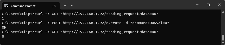
To execute the required command, the user needs to send an HTTP POST request to the following URL:
http://[IPv4]/execute?command=[COMMAND]&process=[PROCESS ID*]&val=[VAL*]&opt=[OPT*]
HTTP API commands listed below are available in all unicontrol versions.
| [COMMAND] | Command parameters | Note |
|---|---|---|
D0-D8 | [VAL] can assume values ranging from 0 for LOW to 100 for HIGH. [OPT] and [PROCESS ID] are ignored. |
If the respective digital pin is listed as output (OUT) on the Peripheral page, execution of the command will change the respective pin's state to [VAL], where 0 stands for logical LOW, 100 for logical HIGH
and values between 1 and 99 will result in a PWM (analog) output with [VAL]% duty cycle. |
RE1-RE12 | [VAL] can assume values 0 for LOW and 1 for HIGH. [OPT] and [PROCESS ID] are ignored. | If the Shift register is available, execution of the command will change the respective register pin's state to [VAL]. |
MEM1-MEM8 | [OPT] must be between 1 and 3. For [VAL] only values between 1 and 100 will be accepted. [PROCESS ID] is ignored. |
Executing this command will modify the respective memory slot based on [OPT] parameter. The value stored in the memory is increased by (if [OPT]=1), decreased by (if [OPT]=2) or set to (if [OPT]=3) the value of [VAL]. |
process_out |
[PROCESS ID] must be greater than 0 and lower of equal to the total number of processes. [VAL] can only assume 0 for ON state or 1 for OFF state. [OPT] is ignored. |
Sets the output of the process selected in [PROCESS ID] to the state provided in [VAL]. |
reboot |
[VAL],[OPT] and [PROCESS ID] are ignored. | Reboots the device. |
reconnect | Reconnects to the saved wireless network and to the MQTT broker if applicable. | |
factory | Resets all device settings to its factory values. |