
On/Off event
The On event and Off event options determine the events leading to a change in the output's state.
These events may be represented by a change of state of the underlying digital input, an internal timer or satisfaction of a predefined condition.
What follows is a listing of all available events with their respective [VALUE]:
| [VALUE] | On | Off | Event |
|---|---|---|---|
0 | ✓ | ✓ | none |
1 | ✓ | ✓ | Rising edge |
2 | ✓ | ✓ | Falling edge |
3 | ✓ | ✓ | Condition |
4 | ✓* | Deadband (standard) | |
5 | ✓* | Deadband (mid-range) | |
7 | ✓ | ✓ | Timeout |
9 | ✓* | Analog link | |
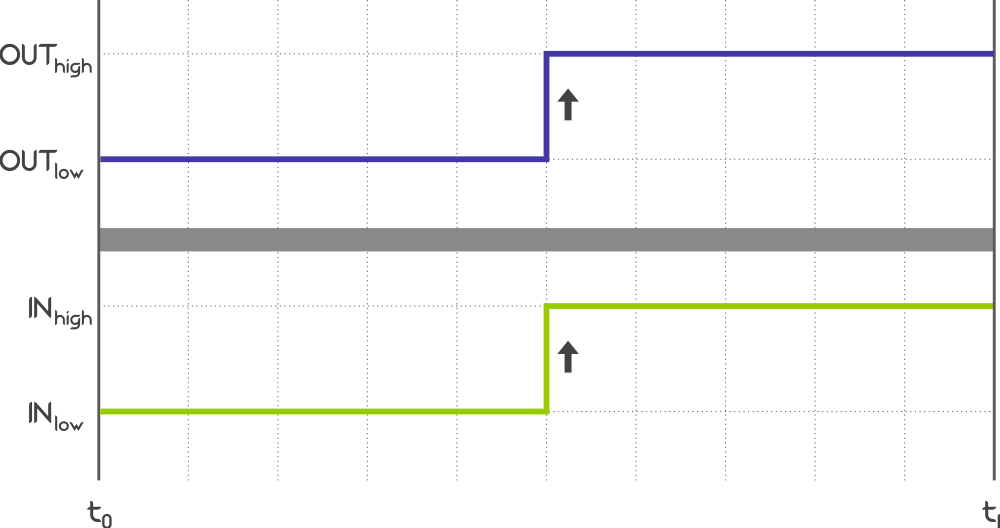
Rising edge
A Rising edge is a standard trigger suitable for a wide array of digital inputs.
The output assumes a predefined state following the change of input from LOW to HIGH,
applying Control period, Delay and Fader*.
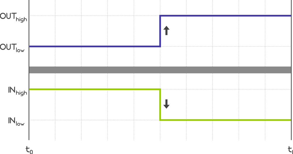
Falling edge
A Falling edge, similarly to the Rising edge, is a standard trigger suitable for a wide array of digital inputs,
often complementing the Rising edge in a single application.
The output assumes a predefined state following the change of input from from HIGH to LOW,
applying Control period, Delay and Fader*.
Condition
A Condition is a standard trigger suitable for a variety of analog inputs. The output changes from LOW to HIGH once the condition is evaluated as TRUE,
applying the Control period, Delay and Fader*.

FALSE and then TRUE again.Selecting this option in the On event drop-down menu enables an additional row for setting up the test Condition.
Deadband
A Deadband control acts as a simplified, two-way Condition, suitable for a wide range of basic applications where the input needs to be maintained within a predefined range.
Depending on the Out on when option, the output is turned ON (or OFF, respectively) when the input value falls below (or rises above, respectively) the deadband range,
with the Control period and Fader* being applied.
There are two options for defining the Deadband range.
- If the
Deadband (standard)option is selected, the range is directly defined by providing Low and High values. - If the
Deadband (mid-range)option is selected, the range thresholds are calculated by either adding or subtracting the Tolerance to/from the provided Mid point.

Below selected.
Above selected.
Deadband (standard) or a Deadband (mid-range) in the On event,
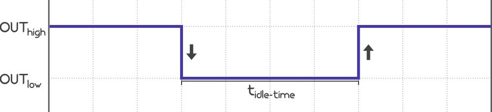
the Off event row disappears from the process options.Timeout
A Timeout is a simple trigger changing the output from LOW to HIGH (or from HIGH to LOW, respectively)
after a predermined idle-time passes while being LOW (or HIGH, respectively) regardless of the cause of the initial state change.
Analog link
An Analog link is a direct, real-time translation between an analog input and a PWM output.
Selecting an Analog link in the On event drop-down menu hides the Off event as the Analog link is a
two-way control not allowing combination with other events.
When selected, the output is evaluated multiple times per second and is set to a value between Low output and High output
depending on the immediate input reading and its relative position within the range between Low input and High input
based on a linear interpolation.
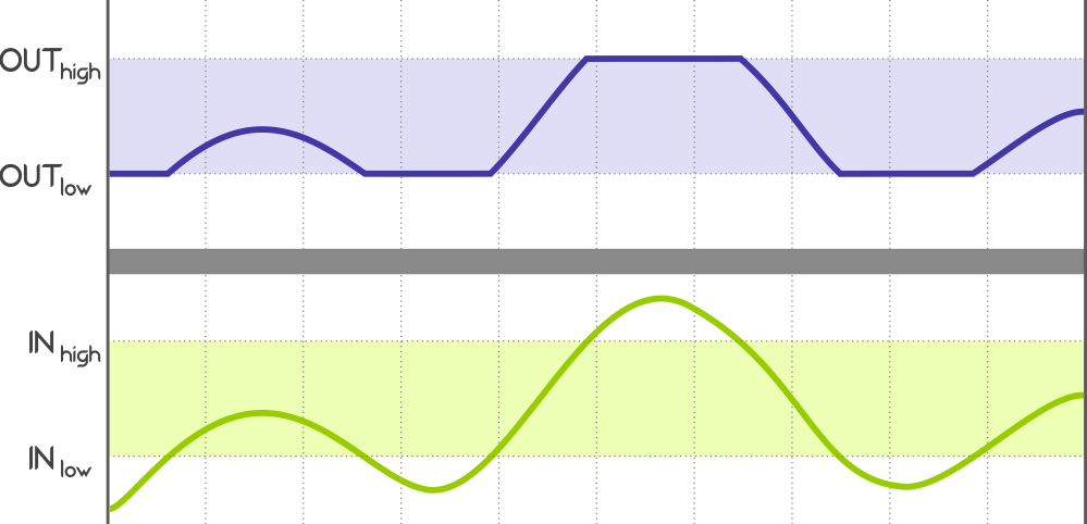
Low input and High input, then the output is a linear combination of Low output and High output.Analog link in the On event, the Off event row disappears from the process options.HTTP
The device will accept HTTP requests at the following URLs related to:
- On event:
(POST) http://[IPv4]/var_set?param=onevnt_[PROCESS ID]&val=[VALUE]
(GET) http://[IPv4]/var_request?param=onevnt_[PROCESS ID]
- Off event:
(POST) http://[IPv4]/var_set?param=offevnt_[PROCESS ID]&val=[VALUE]
(GET) http://[IPv4]/var_request?param=offevnt_[PROCESS ID]
POST: http://192.168.1.255/var_set?param=onevnt_11&val=1
will set the Process #11 output to turn
ON following the Rising edge recorded on the input.
Learn more in HTTP API.
MQTT
This parameter cannot be accessed via MQTT. Learn more in MQTT API.