
Connectivity
Accessing a bare ESP8266ESP32-S3 can be challenging as they lack physical interfaces, such as a touch display or keyboard. To make up for this deficiency, there are multiple distinct ways the unicontrol device can be accessed, each with varying capabilities. First, there are basic or emergency methods for accessing a new or otherwise inaccessible device:
- Wi-Fi AP mode allows for wireless connection to the ESP8266ESP32-S3 using a computer or mobile device.
- Serial port takes advantage of a USB cable connection to a computer.
Once an Ethernet or a stable wireless STA connection to the network is established, there are three main protocols available for communicating with the device:
- Web interface is the main, user-friendly option for the complete device setup during installation or maintenance.
- HTTP API provides complete control over all aspects of the device using an exhaustive set of HTTP requests, ideal for integrating the device with third-party overarching systems.
- MQTT API enables access to basic telemetry, parameters, and commands over the network or the internet, making it ideal for daily use.
Ethernet
The unicontrol's Ethernet connection is specifically designed to allow reliable communication with the device via the Web interface, HTTP API, or MQTT API using cable and with no compulsory prior network set-up. This mode is particularly useful when the device is fitted with the compatible W5500 mini module and the cable connection is available.
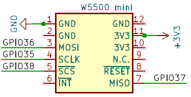
Whenever the W5500 module is available and it is connected to the network via an Ethernet cable, the unicontrol will automatically maintain connection to the network. The IP address assigned to the device can then be found either via Serial interface, Display, or the router's client list.
Wi-Fi Station mode
The Wi-Fi STA mode is the standard operation mode of the unicontrol device, which is the device's primary operating mode. In this mode, the device connects to a wireless network and becomes accessible wirelessly within the local network via the Web interface, HTTP API, or MQTT API.
By default, the device will notify its user of an active connection to one of the saved wireless networks by shortly flashing its on-board LED two or three times every 10 seconds. If the System LED flashes only once in its 10-second cycle, the connection is missing, and user intervention may be needed.
OFF by default,
arbitrarily changeable with the System Button during runtime, always reverting to the default state after reboot.
Wi-Fi Access Point mode
The unicontrol Wi-Fi AP mode is specifically designed to allow access to the device via standard channels, such as the Web interface or HTTP API without relying on any network infrastructure. This mode is particularly useful when the device is newly Flashed with unicontrol software, reset to factory defaults, or when the Wi-Fi STA connection has been lost for any unforeseen reason. In AP mode, the device behaves as an independent Wi-Fi Access point, making itself easily accessible without depending on established networks. There are two options for activating this mode:
- Short-press the System Button (exited by pressing the same button two more times).
- Send the
wifi APcommand via the Serial port (ended by rebooting or sending thewifi STAcommand).
STA, AP, and OFF modes.
If the display's screensaver mode is active, the first brief press deactivates the screensaver before the cycle can proceed.
To connect to the device's wireless network, use the following credentials:
- SSID: The device Name with the addition of the suffix
AP(default:my_uniAP). - Password: The device Password (default:
passw123).

Once connected, the most crucial Device, Security, and Wi-Fi
settings of the unicontrol can be accessed at the address 192.168.1.1, as shown in the screenshot below.

Serial port
The Serial port interface is designed to provide a last-resort access method to the device. In addition to providing debugging information via the Serial port, the device accepts commands listed in the table below.
wifissid1 mynewpass.
| Command | Parameter | Action |
|---|---|---|
wifissid1 | [WIFI SSID] | Changes the SSID of the primary wireless network to [WIFI SSID]. |
wifipass1 | [WIFI PASSWORD] | Changes the password of the primary wireless network to [WIFI PASSWORD]. |
wifissid2 | [WIFI SSID] | Changes the SSID of the secondary wireless network to [WIFI SSID]. |
wifipass2 | [WIFI PASSWORD] | Changes the password of the secondary wireless network to [WIFI PASSWORD]. |
eth | info | Returns basic information about the current network connection via Ethernet cable. |
reset | Reconnects to the network and MQTT broker (if applicable) via Ethernet cable. | |
reset | eth | |
wifi | info | Returns basic information about the current connection to the wireless network. |
STA | Changes the device's Wi-Fi to STA mode. | |
AP | Changes the device's Wi-Fi to AP mode. | |
OFF | Disables Wi-Fi. | |
reset | Reconnects to the saved wireless network and MQTT broker (if applicable). | |
reset | wifi | |
| - | Reboots the device. | |
factory | Resets all device settings to their factory values. |