Mapping (edit)
The native ADC measurement returns a 10-bit value in the range of 0-1023
which is not sufficient for measurements where the desired value is not a linear function of the voltage reading, say, an NTC Thermometer:
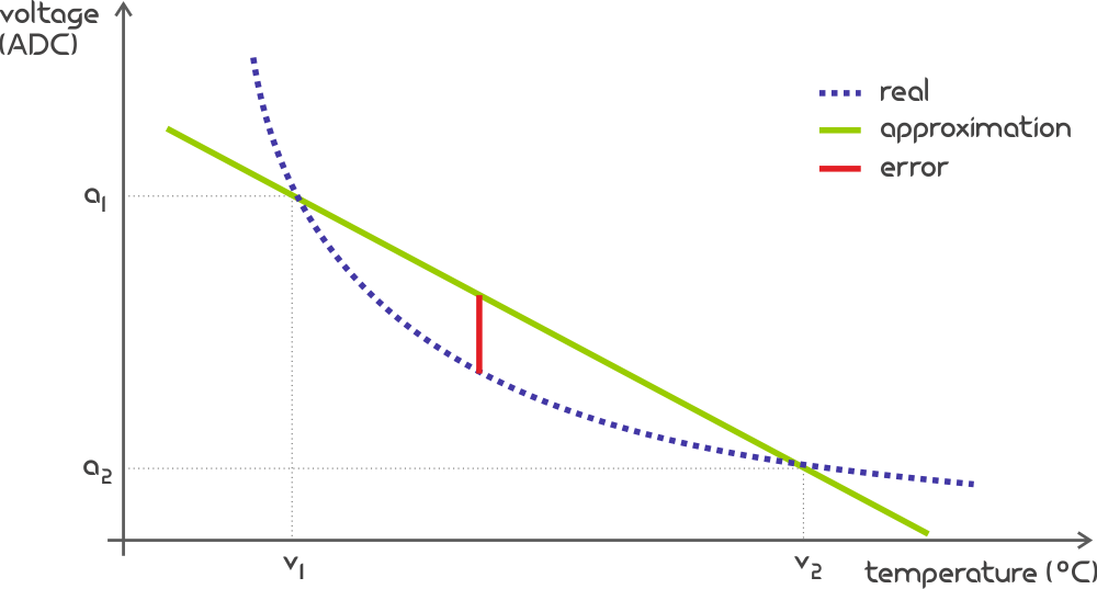
Value Mapping consists of pairs of Analog-Digital Converted (an) and Target Unit (vn) values
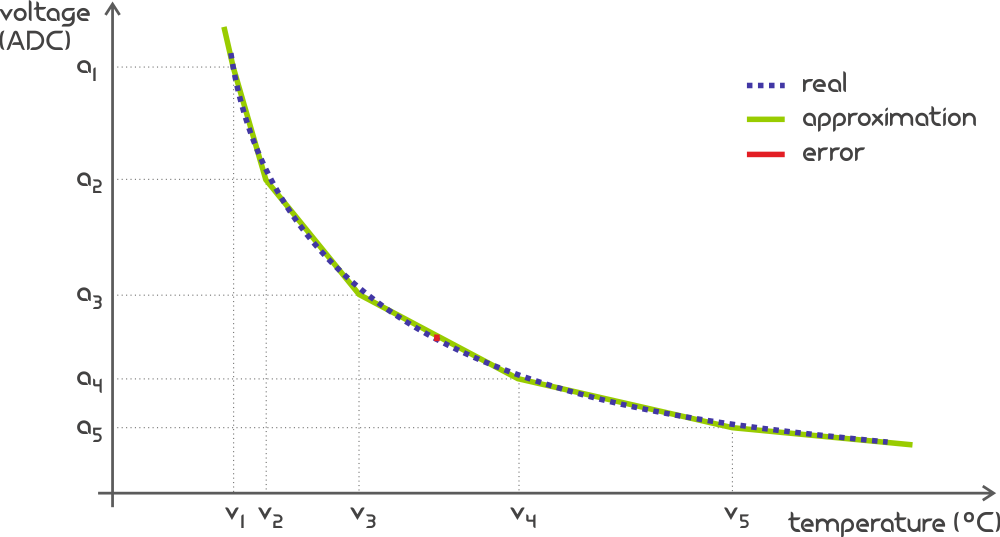
and serves to improve the approximation when transforming readings from ADC to other units by breaking down the total curve into
a maximum of 49 smaller segments within which the linear interpolation leads to a sufficiently small error:
| ADC Value | Target Unit Value |
|---|---|
| a1 | v1 |
| a2 | v2 |
| a3 | v3 |
| a4 | v4 |
| a5 | v5 |
| ... | ... |
| a50 | v50 |
an-vn pairs is 50 but user may define any number of pairs smaller than that, leaving the remainder unused.Editor
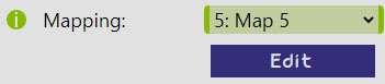
While you may choose a defined Mapping directly within the Peripheral page, you need to visit the Mapping editor to define them.
This is achieved by clicking the Edit button below the chosen map in the Peripheral page:
Once in the Mapping editor, the user needs to provide following:
Name- user-defined name of the Mapping for better orientation,Sign- symbol representing a unit of measurement (e.g. °C, °F, % etc.), andPairs of ADC/Mapped values- up to 50 combinations ofADCnvalue with their Mapped counterpart constituting the whole curve. TheADCnseries does not need to be regular, but it must be an increasing series, and it is recommended to provide only a range of values that can be practically obtained. If theADCreading falls outside of the provided range, it is considered an invalid reading and a Safety Shut-down is initiated.
All of this can be provided either by manually filling in the input areas within the Mapping editor or by providing it in the JSON form. This is done as follows:
- Click on the "JSON Import / Export" button - this will unhide the
JSONtextarea - Paste the JSON into the textarea
- Click on the "Load from JSON - this will feed the
JSONdata into the input areas above
JSON needs to be in the following structure:
- {
- "name":"[MAPPING_NAME]",
- "sign":"[MAPPING_UNIT_SYMBOL]",
- "a1":[a1],"v1":[v1],
- "a2":[a2],"v2":[v2],
- ...
- "an":[an],"vn":[vn]
- } , with n anywhere between 2 and 50
Example
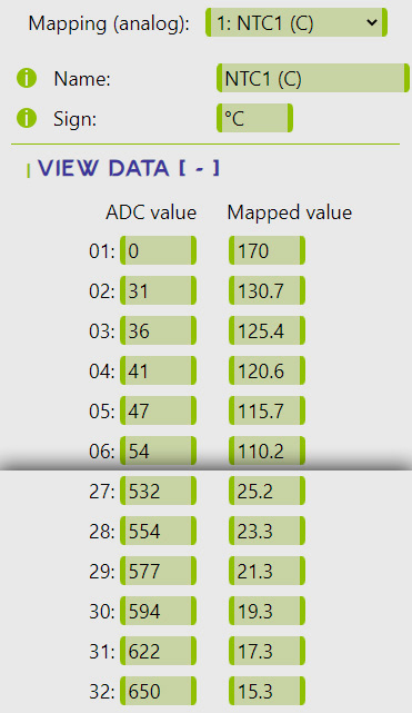
Consider a following Mapping example for an NTC Thermometer and an instantanous voltage reading corresponding to an ADC value of 562.
The nearest lower and upper mapped ADC values as per the example are 554 and 577, respectively.
These are corresponding to the Mapped values of 23.3°C and 21.3°C, respectively.
The raw transformed value (prior to Calibration) is then calculated as a linear interpolation of the range 23.3°C - 21.3°C
based on a relative position of the ADC value of 562 in the range of 554 and 577, which results in 22.6°C.