Special I/O
The unicontrol lets you take advantage of a wide variety of hardware configurations, but there are still situations and applications where the default set of peripherals are not sufficient. You may extend this using a combination of correct wiring and set-up in the In-out menu by:
- Shift register with up to 9 additional digital outputs,
- Analog multiplexer with up to 7 additional analog inputs, and
- TFT Display.
Shift Register
The basic ESP8266 I/O set-up may be enhanced by additional digital outputs using a Shift register.
Currently the only supported and tested hardware configuration is with a 74HC595 integrated circuit.

Shift register in unicontrol is activated automatically once the following selections are made in the In-out menu:
SR - SRCLKforD5,SR - SERforD7, andSR - RCLKforD8:

Upon activation, RE1 through RE12 digital outputs appear as available choice in the Input source,
Output and Variable constraints drop-down menus.
RE1 - RE12 outputs are slow (only refreshed several times per second) and are not capable of PWM. This makes them unusable for applications dependent on PWM like LED dimming. You may, however, easily use them for simple HIGH/LOW output applications like controlling a relay.RE1 - RE12 are pure outputs and cannot serve as external inputs, their output state can be used as an artificial input in another processes or constraint.Available configurations
There are two possible configurations related to using the 74HC595 unit. The first option is to only use one 74HC595 which,
as seen on the diagram, unlocks the RE1 through RE8. Adding the second unit will further expand the set-up capabilities by RE9 - RE12 outputs and an analog multiplexer (pins A, B and C)

In the software configuration these two cases are not differentiated as unicontrol always assumes both units are connected. In case of only one unit available, using outputs RE9 - RE12 will have no effect and inputs I1 - I8 will all return same A0 value.
74HC595 is only appended to the first one and shares no direct wiring with the ESP8266 board.Analog multiplexer
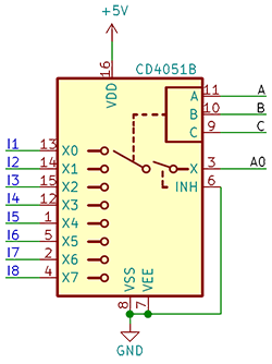
By activating the Shift Register, an Analog multiplexer becomes automatically available as well.
This expands the analog input capabilities from a single A0 pin to 8 independently monitored analog channels I1 - I8.
While the officially supported is the CD4051B multiplexer, any multiplexer with at least 8 channels may be usable for this purpose.

CD4051B unit are the wiring counterparts to the equivalently labeled pins of the second 74HC595 module.For the correct wiring, please follow the diagram below together with the diagram of the Shift Register. Please note that both register units need to be connected as a pre-requisite for the Analog multiplexer.
As long as the Shift Register is enabled no additional software configuration is needed for the multiplexer pins I1 - I8 to be readilly available for use in the Input source,
Output and Variable constraints drop-down menus as well as in the In-out menu.

TFT Display
To obtain a permanent overview of the system and processes it is possible to connect and utilize a standard TFT display. Any monochromatic 128x64 display communicating with a I2C protocol should be compatible and follows the wiring below:
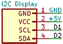
The display is activated in the software automatically once the following selections are made in the In-out menu:
Display - SCLforD1, andDisplay - SDAforD2.

Activating a display will start a loop in which the module repeats indefinitely a set of information screens with crucial information about module's operation like WiFi and MQTT connection status, system clock and more:


Outside of the regular loop, display will also show alerts of important system events like connection or disconnection of the WiFi, subscribing to MQTT etc.

Activating a display also unhides a Show display option in the Process menu. Enabling this will include basic information about the selected process into the display loop, notifying about current input and output:

Change of the output state will then also trigger an alert:
