
How it works
In order to use the unicontrol device efficiently, it may prove very helpful to first understand its basic principles to avoid confusion and fully comprehend its capabilities and limitations.
The unicontrol operates on an event-driven basis, which means that its built-in algorithms make decisions based on dynamic changes in inputs, rather than just their static states. With few limitations, this allows for multiple "rules" to control a single output simultaneously, and also for a single "rule" to manage multiple outputs.
ON at all times when then temperature is below 20°C, the programming reacts to the moment when the temperature crosses the 20°C threshold.
It does not force the output to be ON for the whole duration, so that it can be freely turned OFF by other events, such as:
- a secondary thermometer reaching a certain reading,
- a timer running out,
- a user command arriving via HTTP, MQTT or web interface, or
- a button being pressed..
Note: All of the above events may be defined at the same time.
ON for the entire duration, it can be immediately stopped by another event, such as:
- an end-stop being triggered,
- a safety reflective sensor being activated,
- a user command arriving via HTTP, MQTT or web interface, or
- an emergency button being pressed.
Minor deviations from this rule in specific cases exist to ensure intuitive behavior, which will be discussed in the following sections.
The Process
The primary computing and evaluation unit in the unicontrol system is a single Process, which represents a single "rule" or algorithm defining an input-output dependency and its precise behavior. A device's capabilities are determined by the number of Processes it can handle simultaneously, either 5, 15, or 40, based on the uploaded version. Processes are evaluated multiple times per second in discrete time, with each individual evaluation referred to as a Loop. The evaluation monitors the static states of relevant parameters and captures any changes that occur between individual Loops. These changes represent the switching events.
ON (or OFF) based on the Rising edge (or Falling edge) detected on the input switch.
The evaluation of the process, expressed through individual loops, may appear as follows:
- Loop 1: Input is
LOW(no previous reading) -> no action - Loop 2: Input is
LOW, same as before -> no action - Loop 3: Input is
HIGH, previous reading wasLOW-> Rising edge switching event is recorded, lights are turnedON - Loop 4: Input is
HIGH, same as before -> no action - Loop 5: Input is
HIGH, same as before -> no action - Loop 6: Input is
LOW, previous reading wasHIGH-> Falling edge switching event is recorded, lights are turnedOFF - Loop 7: Input is
LOW, same as before -> no action
The following flowchart outlines the Process algorithm executed in a single Loop.
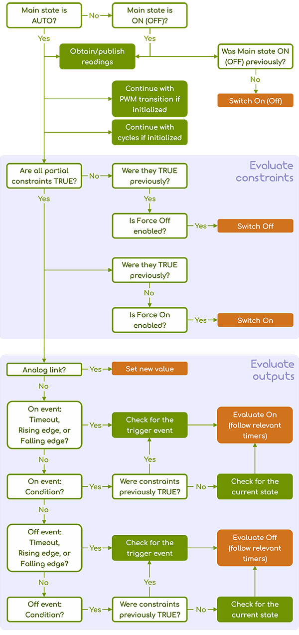
The above implies that the process does not constantly evaluate its outputs. For the regular evaluation of any given process output to occur, two necessary prerequisites must be satisfied:
- Main state of the given process must be set to
Auto, and - All Constraints associated with the respective process must be met at the same time.
In addition to Auto, there are three more Main states that the process can assume:
On- When theOnstate is assumed, the output is switchedONone time.Off- When theOffstate is assumed, the output is switchedOFFone time.Inactive- In this state, the process and all assigned inputs and outputs are not considered in any way.
In both On and Off states, the process continues to collect and publish the assigned input, if allowed and
the possibility of manual control over the outputs, if defined, is also maintained.
- combine multiple inputs,
- build compound rules for controlling the outputs, or
- define various sequences.
Constraints
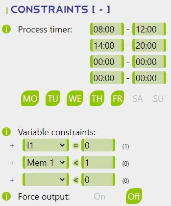
Constraints serve as the primary limitation determining the extent to which a Process's evaluation will advance within a single Loop as per the flowchart above. Effectively, they decide if the respective Process's outputs are responsive, as they determine whether the evaluation will reach the Event testing stage. Constraints consist of the following partial conditions:
- Four independent Time frames. Current real time must fit into at least one of them.
- Days of the week. Current day as per the real time obtained from the internet must be enabled.
- Up to three User-defined conditions based on available readings or states.
These Constraints are considered as a whole, and to evaluate the respective process's output, all partial conditions (if relevant) must result as TRUE.
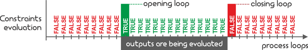
The Loops in which the Constraints start or stop being satisfied play a significant role in the overall behavior of a Process.
If enabled, the Force On option will automatically switch the process ON
when the Constraints are satisfied for the first time after they were previously unmet (i.e., on the Opening loop).
Similarly, if enabled, the Force Off option will automatically switch the process OFF
when the Constraints are not met for the first time after they were previously satisfied (i.e., on the Closing loop).
Both Force On and Force Off options can trigger Secondary outputs if applicable.
08:00 and 20:00.
At 20:00, the process ceases to evaluate the output; if the light is ON at that time and Force Off is disabled,
it will remain ON until manually turned OFF or triggered by the process the following day after 08:00.
Enabling Force Off automatically switches the lights OFF at 20:00,
regardless of the process input or switching events.
Input
A process can only have one main input that is tested for the switching events. The input can be any valid peripheral or memory slot, and there are several options available to define what information to collect and how it will be collected.

The Input source selects the primary peripheral,
and if a digital GPIO is chosen, the Channel option allows differentiation between various values available on the same Peripheral, if relevant.
Additionally, there are three more options dedicated to publishing live readings to the MQTT broker, including Allowing publishing, setting the Frequency for sending these messages, and embedding the process name into the message topic using the Subtopic button. See the MQTT telemetry and Input settings for further details.
Output
Similarly to the input, each process can have a single Primary output with the option to expand using up to three additional Secondary outputs. These outputs behave differently and provide extra flexibility in defining contingencies or sequences.
The Publish and Subtopic options relate to publishing the output state to the MQTT broker, and messages are sent immediately on each state change or in ten-minute intervals as long as the states are not changing. See the MQTT telemetry and Output settings for further details.
Further output options and capabilities vary depending on the Primary output's Peripheral choice and can be divided into three groups:
- Shift register RE1-RE12 - as the most basic logical output, they only have a single
Invert option that can be used to invert the
HIGHandLOWoutput states for accommodating different methods of wiring. - Digital GPIO D0-D8 - represent the raw digital output pins of ESP8266. As they are capable of PWM, they carry
extra options to enable the PWM output and set the Duty cycle.
Also, the Invert option can be used to invert the
HIGHandLOWoutput states. - Memory slots MEM1-MEM8 - represent integers saved in RAM. They can be used for counting or exchanging information between processes. The Action option allows you to define what to do with the saved value when the On event is triggered (the Off event is ignored). The Mem value determines a constant that will be used for the underlying memory operation, depending on the chosen Action.
Safety Shut-down
Starting with version 1.10, each non-logical input now includes an indelible Safety Shut-down feature.
If the sensor assigned to a particular Process is unable to provide a valid reading, or if specific conditions suggest an invalid reading,
this feature automatically switches OFF all Outputs linked to that Process.
This function operates by emulating the satisfaction of the criteria for a standard Off event,
with both the Delay and Control period being applied before the execution of the Safety Shut-down.
Furthermore, any invalid sensor reading will instantly halt all activities related to input, resuming only when valid values are once again available.
This feature applies to the following sensors:
- DS18B20 Thermometer - Unresponsiveness of the sensor or bad readings trigger this feature.
- DHT Sensors - Unresponsiveness of the sensor or bad readings trigger this feature.
- SR04 Ultrasound Sensors - A series of 6 or more consecutive readings that fail to meet the following criteria
triggers this feature for an instantaneous reading (
Channel 0):- The obtained reading must fall within the measurement range of the selected sensor.
- The obtained reading must be within 10cm of the previous readings.
- The obtained reading must be within 20cm of the previous two readings.
Channel 1), this feature is triggered if at least 25 consecutive readings fail to meet the provided criteria. - ENS160 + AHT21 Combined Sensor - Unresponsiveness of the sensor or bad reading triggers this feature.
- Analog Input - Raw
ADCreadings that fall outside of the defined Mapping range are immediately deemed invalid.
N/A. Timers
There are several built-in timers that provide maximum control over the process' behavior. These include:
- Timeout is an independent switching event that automatically switches the output
ONorOFFafter a predetermined time in the opposite state has elapsed. Timeout is provided independently forONandOFFstates. - Control period refers to a specific time interval during which an input must maintain a particular state or remain within a specified range of values
(depending on the selected switching event) before the event is ultimately recognized. If the state or value is lost before the timer expires,
the intended action will be cancelled. This timer does not distinguish between
ONandOFFstates. - Delay timer ensures that once a switching event is recognized (in accordance with the Control period),
the output waits for a specified duration before assuming the desired state. Unlike the Control period, any subsequent changes in the relevant input before the
timer expires will not affect the Delay timer; in other words, losing a specific state will not cancel the action executed at the end of this timer.
The Delay timer is provided separately for
ONandOFFstates. - Fade timer only applies to PWM output. The Fade-in and Fade-out periods determine the time frame during which
the transition between two states will be performed. Setting this will initiate the PWM transition upon a state change instead of immediately assuming a constant output.
Fade timer is provided independently for
ONandOFFstates.

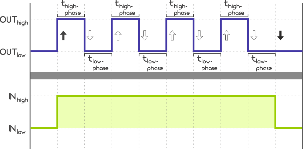
- Cycle timer allows repeated phasing between
HIGHandLOWstates, or simply "blinking", of the output as a replacement for a constantONstate (theOFFstate remains constant). Setting this will initiate the cycler upon a switchONinstead of assuming a constantONstate. Cycle timer is provided independently forHIGHandLOWphase.
Further reading
To further expand your understanding, you may follow the links below:
- unicontrol-software-1st-part: The first part of our beginner's guide for unicontrol.
- unicontrol-first-init-2nd-part: The second part of our beginner's guide for unicontrol.
- unicontrol web interface reference: A complete technical documentation of ayatec interface
- Tutorial - First boot: Navigate through your first moments with unicontrol