Default hardware
The unicontrol lets you take advantage of a wide variety of hardware configurations with an ESP8266 board at the core.
Compatible boards
In essence, the unicontrol software is compatible with any ESP8266 board with Flash memory of 4MB or more. This software has been tested and verified on multiple boards as follows (not exhaustive):
| Development boards and chips | Compatibility | |
|---|---|---|
| Assumed | Tested | |
| ESP-03/05/07 (4MB) | ✓ | |
| ESP-07S | ✓ | |
| ESP-12 (ESP8266MOD) | ✓ | |
| ESP-12E/F | ✓ | ✓ |
| ESP-12S/Q | ✓ | |
| ESP-202 | ✓ | |
| ESP-WROOM-02D/U (4MB) | ✓ | |
| Wemos D1 Mini* / Mini Pro / Pro all versions | ✓ | ✓ |
| Wemos D1 R1 | ✓ | |
| NodeMCU v0.9 | ✓ | ✓ |
| NodeMCU v1.0 | ✓ | ✓ |
| NodeMCU v2 | ✓ | |
| Adafruit HUZZAH ESP8266 | ✓ | |
| Modules | Compatibility | |
| Assumed | Tested | |
| ESP-12E/F/S Relay Module 2/4/8 Channel | ✓ | ✓ |

The unicontrol is capable of controlling the full hardware capabilities on any ESP8266 - based development boards, applying individual boards' limitations. In the basic configuration, you may control the following I/O:
| Pin | GPIO | Default function |
|---|---|---|
| D0 | 16 | Digital OUT |
| D1 | 5 | Display - SCL |
| D2 | 4 | Display - SDA |
| D3 | 0 | Digital OUT |
| D4 | 2 | System LED |
| D5 | 14 | Digital IN |
| D6 | 12 | Digital OUT |
| D7 | 13 | Digital IN |
| D8 | 15 | Digital OUT |
| A0 | ADC0 | Analog IN |
Please check the Peripheral page to find out more about hardware setup possibilities.
Basic I/O
Following the listings above, in the basic configuration you may use the available on-board GPIOs as:
Plain digital output,Plain digital input, andAnalog input.
Plain digital (logical) output
The first and most obvious capability of unicontrol is connecting a basic HIGH / LOW-output type device to the ESP8266 board and control it via turning a GPIO pin on and off according to a pre-set timer, external command or any measurable event.
With a minimum set-up (using a relay, mosfet or nothing at all) you may for example:
- open or close a house gate or garage door,
- turn any light (including LED) on and off,
- dim an LED/LED stripe, or
- switch a fan, water pump, or any other 100/230V device on and off.
HIGH, LOW, or specific PWM output on a predefined pin.D0-D8) can be used as digital output, all capable of PWM.
This may, however, be expanded using the Shift Register to a total of 18 independent digital output pins, 6 of which retain the PWM capability.Plain digital (logical) input
All ESP8266 GPIO pins are capable of reading a basic HIGH/LOW-input type signal and using this information either to control an output or post it online.
With a minimum setup (using a resistor or nothing at all), you may, for example, read the logical state of:
- PIR movement sensor,
- capacitive touch sensor,
- shock or sound sensor,
- mechanical switch or a button, or any other low voltage
HIGH/LOW-based input.
HIGH or LOW value to a connected pin.D0-D8 and A0) can be utilized as a logical input.Analog input
The A0 pin holds a special place among the ESP8266 capabilities as its built-in A-D converter allows it to measure not only a HIGH or LOW state, but also a full range of input voltage from 0 to 3.3.
By connecting a suitable sensor to the A0 pin in a correctly chosen voltage divider configuration, you can measure:
- potentiometer,
- water level in a flower pot,
- light brightness,
- soil moisture,
- temperature, or
- any other analog input measurable with a resistance-based sensor.
A0 is the only pin with a built-in ADC on any ESP8266-based board, you may increase the available input channels to 8 using an Analog multiplexer.System Button
The System button is a pre-programmed ESP8266 GPIO button functionality, which serves exclusively for the most basic system commands, depending on how long it is pressed:
- Short press (shorter than a second with display in screensaver mode): Temporarily disables the screensaver mode.
- Short press (shorter than a second without display in screensaver mode): Toggles between the Wi-Fi modes Station, Access point, and Off.
- Medium press (between 1 second and 10 seconds): Reboots the device.
- Long press (longer than 10 seconds): Performs a factory reset of the device, replacing ALL settings with the factory defaults and reboots the device.
1.16. In this mode, the display only renders alerts but is dimmed otherwise to prevent its excessive wear resulting in loss of brightness or burn-in.
The screensaver mode is initiated automatically after 5 minutes of uninterrupted operation, but only if the Display is in use and the System Button is assigned to I1 or I8.
This timer resets with each press of the System Button. Starting with version 1.17, the display in screensaver mode continues to show status information by briefly flashing a single, double, or triple status dot every 10 seconds, corresponding to one, two, or three flashes of the status LED, respectively.
1.17, the Wi-Fi mode automatically reverts to its default mode after 5 minutes.
By default, the System Button is assigned to the I8 analog input, only accessible with the Analog multiplexer.
However, users can change this to any digital pin from D1 to D7, or the I1 or I8 pins of the Analog multiplexer,
or even disable the button entirely.
Using the System button on any ESP8266 board other than NodeMCU* will require adding the designated hardware button first.
To do so, connect the System button pin (D4 by default) to one leg of the button, and the GND pin to the other as per the schematic below:

FLASH button connecting its D3 pin to GND, which is also usable as the System button.I8 pin.
Alternatively, the same button can be wired via solder-jumper also to the D3 (GPIO0) ESP8266 pin.
System LED
The System LED is a pre-programmed ESP8266 on-board LED functionality, which serves exclusively for the most basic system diagnostics. The information provided by the device can be inferred from the LED sequence as per the table below:
| LED Sequence | Interpretation | |
|---|---|---|
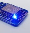 | LED is on (for up to 10 minutes) | The device is booting and, if requested, resetting to factory defaults. |
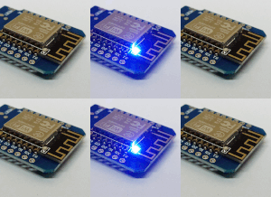 | 10 fast flashes over the course of 2 seconds | The device has booted succesfully. |
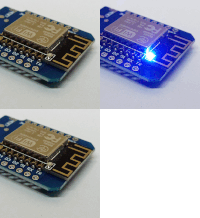 | 1 short flash every 10 seconds | The device is running without an active STA Wi-Fi connection. |
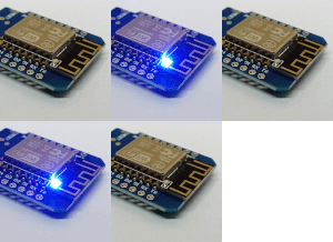 | 2 short flashes every 10 seconds | The device is running and has successfully connected to Wi-Fi (STA). |
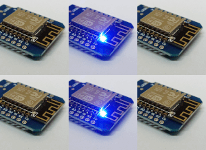 | 3 short flashes every 10 seconds | The device is running and has successfully connected to both Wi-Fi (STA) and MQTT broker. |
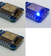 | 1 long flash every 10 seconds | The device is running in the Wi-Fi AP mode or has just been switched to this mode by short-pressing the System button. |
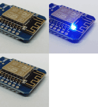 | 1 very long flash every 10 seconds | The Wi-Fi is off. |
 | Rapid flashing over the course of 2 seconds | Reboot and reset to factory defaults is following. |
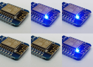 | 4 rapid flashes every second | The System button is pressed and held. |
By default, the System LED is assigned to the D4 pin on the ESP8266 board.
However, users have the option to change this assignment to any digital pin from D0 to D8 or even disable the System LED entirely if not required.
D4 will require adding a hardware LED, including an adequate resistor.D8(GPIO15) ESP8266 pin.

