
Special sensors
In addition to the basic digital and analog inputs described in the Default hardware, following extensions are also supported by unicontrol:
- DS18B20 thermometer: An industrial-grade, precise thermometer that can operate in almost any environment. It has a measurement range of -55°C to +125°C and an accuracy of ±0.5°C.
- DHT11/DHT22 sensor: A widely used temperature and relative humidity sensor for IoT applications.
- 1838 IR Receiver: An infrared signal receiver that allows for remote control capabilities.
- SR04 family of ultrasound sensors: Proximity sensors that accurately measure distances to the nearest physical obstacle from 4 centimeters to 6 meters.
- Pulse sensors: A group of sensors that transform various physical parameters into electrical pulses measurable by an impulse counter, such as pulse water flow meters.
- ENS160 + AHT21: A general-purpose air quality sensor, designed to measure the temperature, humidity, and concentration of CO2e and TVOC in ambient air.
The table below provides comprehensive information on the pinout available for each type of sensor:
| Pin | SR04 | DS18- -B20 |
DHT11 DHT22 |
Pulse sensor | ENS160 /AHT21 | |
|---|---|---|---|---|---|---|
| Trigger | Echo | |||||
| D0 | ✓ | ✓ | ||||
| D1 | ✓ | ✓ | ✓* | ✓ | ✓ | ✓** |
| D2 | ✓ | ✓ | ✓* | ✓ | ✓ | ✓** |
| D3 | ✓ | ✓ | ✓ | ✓ | ||
| D4 | ✓ | ✓ | ✓ | ✓ | ||
| D5 | ✓ | ✓ | ✓* | ✓ | ✓ | |
| D6 | ✓ | ✓ | ✓* | ✓ | ✓ | |
| D7 | ✓ | ✓ | ✓* | ✓ | ✓ | |
| D8 | ✓ | |||||
| A0 | ||||||
**Introduced in version 1.09
The sections below provide detailed information on each of the sensor options outlined above.
DS18B20 thermometer

The DS18B20 is a widely used, industrial grade digital temperature sensor with a measurement range of -55°C to +125°C and accuracy of ±0.5°C.
It comes either as a bare sensor (TO-92 or surface-mount) or in a waterproof packaging suitable for outdoor and other harsh environment applications.
The unicontrol can upport up to 12 independent units, differentiated by the Channel number.
Measurement is performed on a pre-programmed maximum 12-bit resolution ensuring measurements with less than 0.1°C step.
Wiring is done as per the schematic below.

The DATA pin can be assigned to any digital pin from D1 to D7 in the Peripheral window.
However, it is important to note that only one pin can be used; all DS18B20 units must be connected to the selected pin.
DATA pin is connected to either the D3 or D4 pin, it is not necessary to include the 4.7k pull-up resistor.
Measurement begins as soon as the device is properly wired and the Data pin is assigned on the set-up page.
Measurements are taken at predetermined intervals based on the chosen option:
DS18B20 Fast- a new reading is taken every 10 secondsDS18B20 Slow- a new reading is taken every 5 minutes
DHT sensors
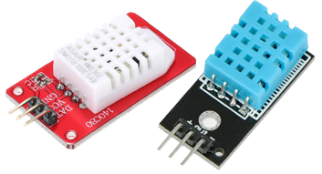
The DHT11 and DHT22 are combined digital temperature and humidity sensors that are commonly used in a wide range of applications,
including environmental monitoring, HVAC systems, and home automation.
DHT22 is an accurate and reliable sensor that can measure temperatures from -40°C to +80°C and relative humidity from 0% to 100% RH, with an accuracy of ±0.5°C and ±2% RH, respectively.
On the other hand, the DHT11 is a cheaper alternative to the DHT22, with a measurement range of 0°C to +50°C and humidity from 20% to 80% RH, with an accuracy of ±2°C and ±2-5% RH, respectively.
Both the DHT11 and DHT22 are compact and durable sensors that are available in various packages,
including through-hole, surface-mount and external shield versions.
The unicontrol can utilize up to eight devices independently, one per each digital pin D0 - D7,
assigned in the Peripheral window.


Measurement begins as soon as the device is properly wired and the Data pin is assigned on the set-up page.
Measurements are then taken every 2 seconds.
Readings can be accessed in two ways based on Channel selection in the respective Process:
Channel 0- latest temperature reading, in °CChannel 1- latest relative humidity reading, in %
1838 IR Receiver

The 1838 sensor is an infrared receiver module commonly used in a variety of consumer electronics and industrial control systems.
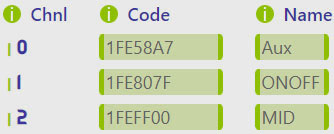
The unicontrol is adapted to utilize the 1838 module to receive user-defined commands from any standard IR remote control including a user-friendly learning procedure.
The sensor typically has three pins for power supply and output signal, wired as follows:

For the Signal pin, a user may choose any of the D1 - D7 pins in the Peripheral window.
It is, however, not possible to use more than one unit of 1838.

The unicontrol can learn up to 8 separate codes differentiated by a Channel selection in the respective Process. Please check IR remote (edit) for a more detailed reference on the learning procedure and usage.
SR04 ultrasound sensors

The x-SR04 family of ultrasound sensors is popular, although they are highly situational sensors.
They allow for the measurement of the physical distance to the closest obstacle and can be used to monitor the presence or the exact position of a selected object with relatively high accuracy.
Common applications include parking sensors in cars, water level monitors, gate position indicators, and general proximity sensors.
The unicontrol supports up to four idenpendent sensors per device and offers high flexibility in GPIO choice.
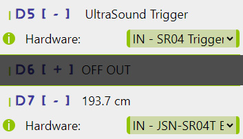
As per the wiring diagram, you need to connect the Trigger and the Echo pins to your ESP8266.
1.16 the unicontrol supports up to four independent SR04 sensors. These sensors must share a common
Trigger pin, but each has its own independent Echo pin.

For the Echo pins (up to four can be defined), a user may choose any of the D1 - D7 pins in the Peripheral window,
with a separate item for the HC-SR04, JSN-SR04T, and AJ-SR04M, due to the slight differences between individual models.
Although both options will read either of the sensors, choosing the correct menu item will lead to the application of the correct limitations.
The Trigger pin is common for all sensors and can be assigned to any digital GPIO.
| Sensor | Distance range |
|---|---|
| HC-SR04 | 4 - 500cm |
| JSN-SR04T | 25 - 600cm |
| AJ-SR04M | 25 - 600cm |
Measurement begins as soon as the device is properly wired, and both the Trigger and the Echo pins are assigned on the set-up page.
Measurements are taken every 0.2 seconds, and only the measured values within the predefined distance range, as per the table above, are considered valid, with all others being ignored.
Readings can be accessed in two ways based on the Channel selection in the respective Process:
Channel 0- Instantaneous reading, updated every 0.2 secondsChannel 1- Average of the last 25 readings, updated every 5 seconds
Values are processed, displayed and published in centimeters, rounded to one decimal place.
Pulse sensors

A built-in impulse counter can be used to collect, process, and publish readings from a wide variety of pulse sensors, which generate impulses as physical parameters are measured. This enables monitoring of a range of physical attributes, such as flow speed or volume, distance or velocity of motion, vibrations, light or sound intensity, or counts of physical events or natural phenomena. A common utilization is found in industrial or commercial settings, where accurate measurement and monitoring of physical parameters is critical to operations. The unicontrol supports up to seven independent counters, tested on frequencies up to 1,000 impulses per second, with a theoretical capability of handling up to 10,000 impulses per second. Standard pulse sensors typically have three pins for power supply and output signal, wired as follows:

The impulses can be counted independently on any of the compatible pins.

For information on setting up and using the impulse counters, please see the Impulse counter (edit) page.
ENS160 + AHT21

The ENS160 represents one of the latest additions to air quality sensors, capable of measuring the concentration of carbon dioxide equivalent compounds (CO2e) and
volatile organic compounds, both having an adverse effect on health and needing to be minimized in homes.
The AHT21 is a complementary humidity and temperature sensor, providing supporting data to the ENS160 for its calculations.
Each unicontrol device can support a single combined ENS160 + AHT21 sensor on the D1-D2 pin pair.
The device needs to be wired to the ESP8266 as follows:

5V supply with at least 1A rating is recommended.
Providing insufficient power will result in highly unstable readings. 
Measurement begins as soon as the device is properly wired and the SCL and SDA pins are assigned on the setup page.
Measurements are then taken every 10 seconds.
There are four different readings accessible via the SCL (D1) pin, differentiated by the Channel selection in the respective Process:
Channel 0- CO2e reading (ENS160), in particles per million (ppm)Channel 1- TVOC reading (ENS160), in particles per million (ppm)Channel 2- temperature reading (AHT21), in °CChannel 3- relative humidity reading (AHT21), in %Channel 4- air quality index (AQI):

For optimal results and user experience, please ensure that:
- Soldering is performed quickly and without excessive overheating of the sensor. The ENS160 sensor is particularly sensitive to overheating when soldered.
- There is sufficient airflow around the sensor. Restricting airflow may lead to more stable readings but at the cost of a slower response to changes.
- The cable connecting the sensor to the ESP8266 is as short as possible (up to 20cm). The I2C protocol requires a stable connection without interference.