First process

In the First boot tutorial, you succesfully accessed your unicontrol device through the Web Interface, which allows you to begin defining its behavior. For instance, you can start with a simple Blinky program.
Peripherals
The initial step in each application the first step is to determine the type of Hardware connected to the ESP8266 GPIO pins.
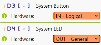
In this tutotial, we will use D3 as a button input (Logical IN)
and D4 as an LED output (General OUT).
The D4 pin (GPIO2) on every ESP8266 features an on-board LED, making it an excellent test output.
It is connected through a pull-up resistor, causing the LED to glow when D4 is LOW and turn off otherwise.
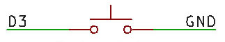
The D3 pin (except when using the NodeMCU board), needs to be connected to the GND via a push-button or a switch according to the scheme below:
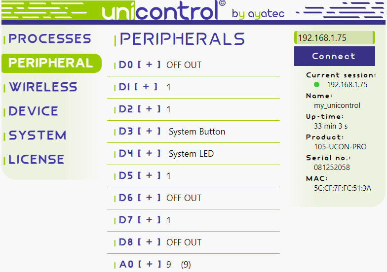
In the Peripheral menu, make the following selections and click Save:
D3:IN - LogicalD4:OUT - General
Process
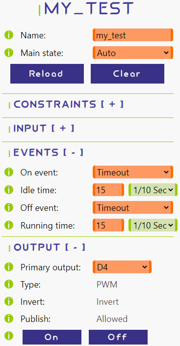
For this task, we only need a single process. To set it up, we can begin with the following configuration:
- Name:
my_test - Main state:
Auto - Primary output:
D4(on-board LED)
To simplify testing, we'll initially exclude the input.
Choose Timeout for both On event and Off event, set 15 x 1/10 Sec (1.5 seconds) for both
Idle time and Running time, and click Save.
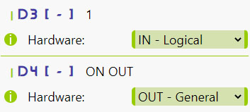
This will make the on-board LED (D4) blink indefinitely at 1.5-second intervals:
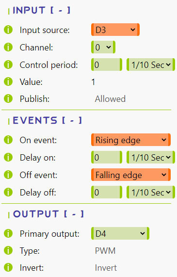
Now that the LED is blinking consistently, we can incorporate user input. Select D3 in Input source, and the process will evaluate the button state.
Choose Rising edge for the On event and Falling edge for the Off event,
so that D4 turns ON when D3 is pulled HIGH and OFF when it is pulled LOW.
Click Save to apply the changes:
D3 and D4 have built-in, enabled pull-up resistors, affecting both the LED and the button.
This may cause confusion in their behavior. As a result, when the button is pressed, D3 is pulled LOW, and when it is released, D3 is pulled HIGH.
Similarly, the on-board LED glows when D4 is LOW and remains off when D4 is HIGH.
So, in the current setup, pressing the button pulls D3 LOW, registering a Falling edge and turning D4 OFF,
which in turn turns the LED ON. Releasing the button pulls D3 back HIGH, registering a Rising edge and turning D4 ON,
which then turns the LED OFF. If needed, you can use the Invert output option to make the LED's logic more intuitive.
In this setup, the button turns the LED ON when pressed and OFF upon release.
You can easily modify this behavior by selecting the Rising edge for both Events and clicking Save.
Then the button will change its state and retain it on each separate button press.
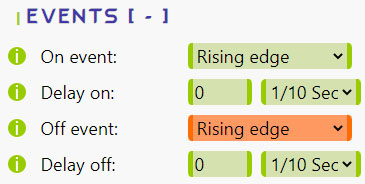
You might also notice that with Rising edge selected for both Switching events,
the button responds to release rather than press-down due to the pull-up resistor connection explained earlier.
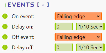
To make the button responsive immediately upon pressing down, try changing both Events to Falling edge.
Don't forget to click Save after making adjustments.