
DIY Project: Bath Fan

The first problem in home automation that I'll address in this DIY series is my bathroom vent fan, which has been irritating me for some time. So far, it has had a traditional setup (at least traditional in my region), where the fan operation is directly bound to the ceiling light switch, with the 230V power supply to the ceiling light serving as the raw signal for the fan to turn on or off. This is often done to overcome a lack of the separate fan switch, but it comes at the cost of very little flexibility. Of course, the user may choose if it should run while the lights are on or turn on once they are turned off together with the run-time, but once the choice is made, the behavior is strictly given. This implies that regardless of the choice, the fan would often run unnecessarily, consuming power and bothering the inhabitants for no good reason. On the other hand, it would often not run when needed, thus failing to do its only job.
Luckilly, this is an easy problem to solve with unicontrol. With its help, I can set the fan permanently to its most basic run mode (run when the signal power is on and vice versa) and fully control it with a remotely operated relay.
Design
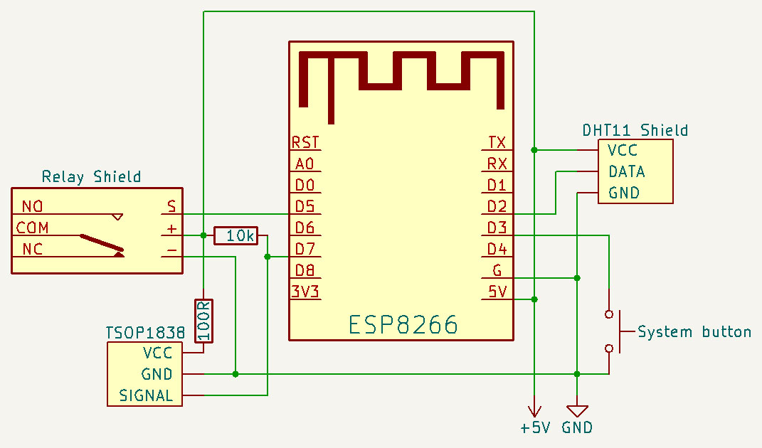
Now that the problem has been identified and the necessary tools selected, it's time to design a solution. Although the unicontrol can operate the fan through MQTT and HTTP commands sent from a smartphone, it's not the most convenient option. I have an IR remote for the ceiling light lying around in the bathroom that can be used to control the fan (thanks to the built-in IR remote support), making it a more practical solution. Additionally, since the ESP8266 will already be in place to enhance the fan's capabilities, why not take it a step further? By adding a cheap DHT11 sensor, the fan can automatically run when the temperature or humidity exceeds a set threshold for a specific amount of time. With this, we'll have much greater control over the fan's functions. All of the above-mentioned features can be achieved with the following scheme:
Components
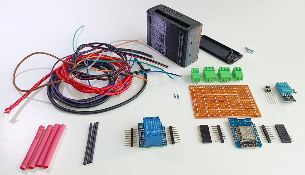
All the components required for the project, according to the scheme above, can be obtained from third-party vendors or printed at home (unicase). Here's an overview of the required components and their price estimates:
| Item | Pcs | Unit price (€) |
|---|---|---|
| ayatec unicontrol mini | 1 | 8.40 |
| ayatec unicase mini | 1 | |
| ESP8266 WeMos D1 mini | 1 | 2 - 5 |
| 5V 1A Power Supply | 1 | 4 - 6 |
| D1 mini Relay Shield | 1 | 2 - 5 |
| DHT11 | 1 | 1 - 3 |
| 1838 Universal IR Receiver | 1 | 0.50 - 1 |
| Prototype Circuit Board 7x5 cm | 1 | 0.20 - 0.5 |
| PCB Terminal Block Connector - 3 pins | 2 | 0.50 - 1 |
| PCB Terminal Block Connector - 2 pins | 2 | 0.50 - 1 |
| 10K Ohm Resistor | 1 | < 0.10 |
| 100 Ohm Resistor | 1 | < 0.10 |
| Tactile Push Button | 1 | < 0.10 |
| Heat-Shrink Tubing | 1 | < 0.10 |
| Scrap Wires/Cables |
The total estimated cost of the components ranges from €25 to €30. However, purchasing the items in smaller bulks instead of single pieces can reduce the total cost to below €25.
Device assembly
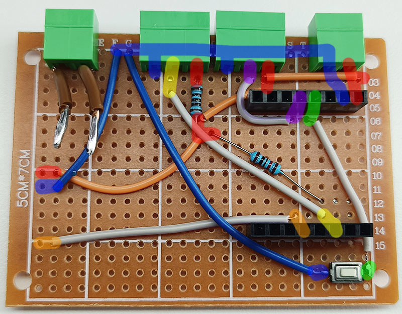
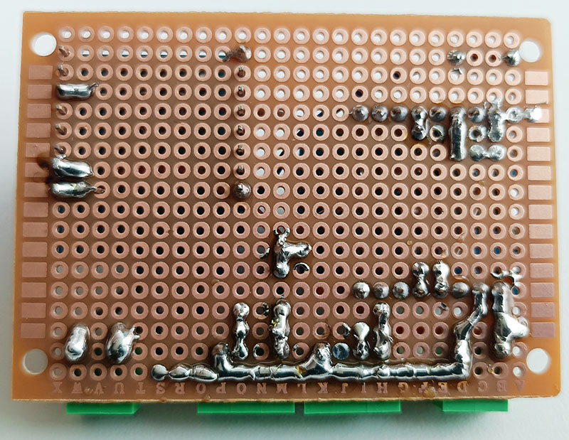
The initial populating of components, as per the provided scheme, is shown in the following photos (the Relay shield and WeMos D1 mini are not included at this stage). Please pay attention to the highlighted sections for a complete understanding of the wiring.

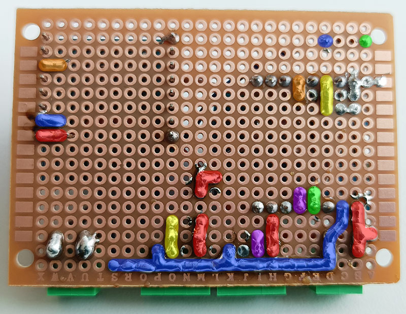
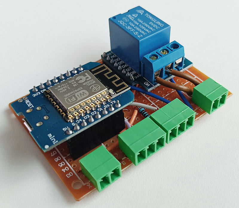
Once the Relay shield and WeMos D1 mini are added, the board assembly will be complete and can be directly fitted into the unicase:


Set-up
After connecting all sensors (the relay is already hardwired) and performing the initial installation and First boot, it's time to set up the unicontrol itself. The first step is to ensure that the connected Hardware is properly defined. To do this, navigate to the Peripherals menu and select the following in line with the scheme:
IN - DHT11forD2OUT - GeneralforD5IN - 1838 IRforD7

After making these selections, clicking Save will immediately take effect.
The temperature and humidity readings will appear next to the D2 section and the Edit button will appear in the D7 section.
Clicking this button will navigate to the IR remote (edit) where the step will take place.
Using this editor, I am going to teach the program which remote code will be used to operate the relay.
In my case, I will only use a single Auxiliary button on my remote, so I will undergo the learning procedure with Aux as the Name
and the Channel left at 0.
After the procedure is complete, the newly learned code will appear in the table as shown below:

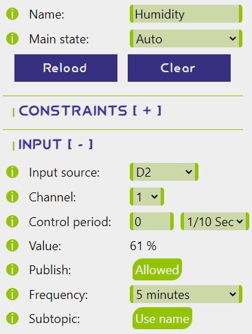
With the hardware fully set up, the next step is to configure the processes. The first two processes will only take care of publishing the DHT11 readings to the MQTT broker, so no outputs, events, or constraints are applicable.
Process 1:- Name:
Temperature - Main state:
Auto - Input source:
D2 - Channel:
0 - Publish (input):
Allowed - Frequency:
5 minutes - Subtopic (input):
Use Name
Same as Process 1 except:

The next two processes will operate the fan so that it can be turned OFF either manually (using the same remote or via MQTT or HTTP command) or after a predefined period of time.
Process 3 will switch the relay on the D5 pin ON and OFF on each IR remote Aux button press. When turning on, it will also trigger the timer on Process 4.
Each state change will be published to the MQTT broker.
- Name:
Vent - Main state:
Auto - Input source:
D7 - Channel:
0 - On event:
Rising edge - Off event:
Rising edge - Output:
D5 - Publish (output):
Allowed - Subtopic (output):
Use Name - Secondary output 1:
(Process) 4: Vent_timer/On -> On
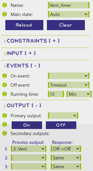
Process 4, after being triggered by Process 3,
will measure the time for which the relay assigned to the Process 3 is ON and will automatically turn it OFF when the predefined period ends.
- Name:
Vent_timer - Main state:
Auto - Off event:
Timeout - Running time:
10 Min - Secondary output 1:
(Process) 3: Vent/Off -> Off

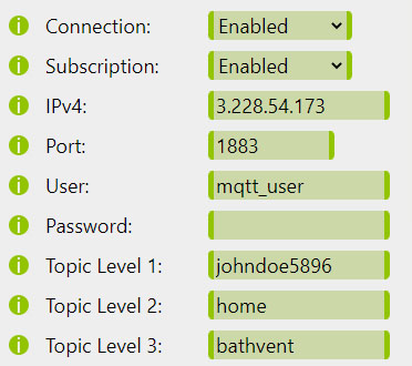
The last thing to address is MQTT set-up. Although it is not necessary for the intended IR remote control, it enhances the capabilities with little-to-no effort. For test purposes, I will now modify the MQTT settings as follows:
- Connection:
Enabled - IPv4:
3.228.54.173 - Topic Level 1:
johndoe5896 - Topic Level 2:
home - Topic Level 3:
bathvent
After making these changes and performing a precautionary reset, the device should now be fully up and running.
Testing
Never forget to test both the hardware and software thoroughly before putting everything back together. Especially the cheaper DHT11 sensors are not really known for their reliability so I am typically letting them run for a week or two before installing them permanently, especially if it would be time-consuming to replace a faulty one.
Simulating all possible scenarios and checking that the process set-up is working as intended is also good practice.
Similarly, it can be helpful to monitor the serial port during testing as it makes debugging much easier.
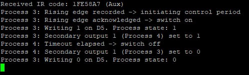
For example, pressing the Aux button on the remote will result in the following series of events visible on the PuTTY console below:
- The
Auxsignal was received. - Process 3 recorded a Rising edge.
- The Rising edge on Process 3 was immediately acknowledged thanks to the
0in the Control period, and wroteHIGHtoD5(fan). - At the same time, it turned
ONthe Secondary output 1 (Process 4), starting its 10-minute Timeout. - After 10 minutes, the Timeout on Process 4 elapsed and turned
ONtheD5(fan).
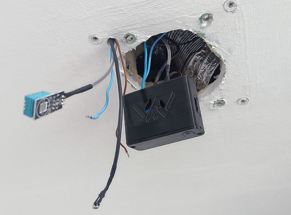
After passing all the tests, the fan could be finally assembled. I chose a neat location for the DHT11 right next to the fan's original side ventilation opening. The 1838 sensor found its place right above the indicator light bulb's "visor".

MQTT Dashboard
To complete my small ecosystem, I will also create an MQTT dashboard that will allow me to monitor the technical status of the device,
readings, and turn the fan ON or OFF if needed while I am away. In total, I have defined the following panels:

- Temperature: subscribed to
johndoe5896/home/bathvent/pub/Temperature/input - Humidity: subscribed to
johndoe5896/home/bathvent/pub/Humidity/input - Local IP: subscribed to
johndoe5896/home/bathvent/pub/ip - Online indicator: subscribed to
johndoe5896/home/bathvent/pub/conn - ON: publish
1tojohndoe5896/home/bathvent/sub/Vent/outset - OFF: publish
0tojohndoe5896/home/bathvent/sub/Vent/outset - RESET: publish
1tojohndoe5896/home/bathvent/sub/reboot
Recording telemetry on the same MQTT topics for Temperature and Humidity using Node-RED will then look like this:

Further improvements
Furthermore, there are plenty of options to further enhance the current set-up by defining additional processes in order to:
- Bypass the timer so that the fan runs until turned
OFFby the user. - Run the fan for different time periods based on which button was pressed.
- Turn
ONthe fan automatically if the humidity or temperature is above the user-defined threshold for a certain period of time. - Run the fan automatically in certain times of the day.
- Automatically reset the device on a regular basis to improve stability.