Output
The Output section is designed to let the user configure how the device responds to recorded events or received commands. Depending on the Primary output choice, the displayed content may vary significantly:
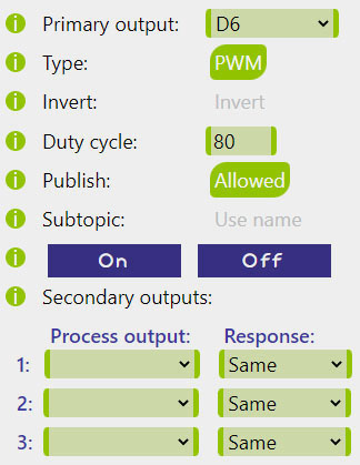
Digital GPIO
The most common Output type is a digital GPIO pin (D0-D8). It supports PWM output,
with the Duty cycle expressed as an integer percentage. The Invert option can be used to turn around the
HIGH and LOW output states to accomodate various wiring options.
Changes of states trigger Secondary outputs and can also be Published with or without
the process Name included in the Subtopic.
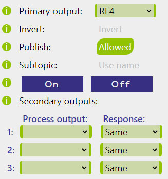
Shift register
If the Shift register is in use, one of its pins (RE1-RE12) can be selected as a simple logical output.
Logical states on these pins are updated 10 times per second, which does not allow the PWM functionality.
Similarly to the digital GPIO pins, the Invert option can be used to turn around the HIGH and LOW output state logic.
Again, changes of states trigger the Secondary outputs and can also be Published with or withouth
the process Name included into the Subtopic.
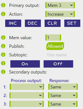
Memory slot
Memory slots represent integers saved in RAM. They can be used for counting or exchanging information between processes. This Output type only responds to the On event (the Off event is ignored), triggering the chosen Action and applying the Mem value if applicable.
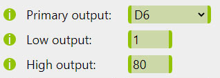
Analog Link
The Analog Link is a special type of switching event that directly translates a range of analog input values into a range of analog (i.e., PWM) output values. On the output side it only requires a pair of duty cycles for the Low and High output as parameters. Publishing and Secondary outputs are not applicable within this option.
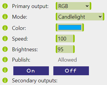
RGB driver
The RGB driver is a special type of Output that renders color programs for RGB or RGBW LED strips.
Each process can carry a separate set of RGB driver parameters: Mode, Color, Speed, and Brightness.
When a relevant Process is turned ON, all four parameter values saved within the process are written into the active RGB parameters
and a corresonding RGB program is rendered.
Alternatively, turning the relevant Process OFF will change the current Mode to 0 (Off).
Changes of states trigger Secondary outputs and can also be Published with or without
the process Name included in the Subtopic.